
Top Essay Writers
Our top essay writers are handpicked for their degree qualification, talent and freelance know-how. Each one brings deep expertise in their chosen subjects and a solid track record in academic writing.
Simply fill out the order form with your paper’s instructions in a few easy steps. This quick process ensures you’ll be matched with an expert writer who
Can meet your papers' specific grading rubric needs. Find the best write my essay assistance for your assignments- Affordable, plagiarism-free, and on time!
Posted: October 23rd, 2024
An Investigation into the Mobilised Bearing Capacity and Head Displacement of Energy Piles
Abstract
We hear “Can you write in APA or MLA?” all the time—and the answer’s a big yes, plus way more! Our writers are wizards with every style—APA, MLA, Harvard, Chicago, Turabian, you name it—delivering flawless formatting tailored to your assignment. Whether it’s a tricky in-text citation or a perfectly styled reference list, they’ve got the skills to make your paper academically spot-on.
Energy piles offer a promising new method of reducing CO2 emissions by utilising geothermal energy to heat and cool buildings. Despite an increase in implementation over recent years a lack of understanding of energy pile behaviour due to thermal effects remains, with current designs either based upon the structural requirements alone or exacerbated safety factors. Existing literature has demonstrated that thermal loading has a significant impact on pile strains. However, little investigation has been conducted into the effect of thermal loading on the mobilised bearing capacity, or pile head displacements which are imperative to the design integrity of the pile and founded superstructure.
This dissertation aimed to assess if varying material properties and increasing thermal loads affect the pile factor of safety and head displacements. A parametric study was conducted where a finite element model, validated against a known field experiment, tested varying values of pile length, pile diameter, soil shear modulus and soil strength under thermal loading. The results of the testing indicated that while the factor of safety showed little variation, pile head displacements were quite sensitive to thermal loads. It was further demonstrated that pile length was the most critical property, as results showed the most significant trend in this data.
It is clear from this research that further industry understanding and formalised design codes are required for the design of energy piles, as the current approach does not account for the substantial change in pile head displacements indicated by this study.
Contents
Yes, completely! They’re a valid tool for getting sample papers to boost your own writing skills, and there’s nothing shady about that. Use them right—like a study guide or a model to learn from—and they’re a smart, ethical way to level up your grades without breaking any rules.
Prices start at $10 per page for undergrad work and go up to $21 for advanced levels, depending on urgency and any extras you toss in. Deadlines range from a lightning-fast 3 hours to a chill 14 days—plenty of wiggle room there! Plus, if you’re ordering big, you’ll snag 5-10% off, making it easier on your wallet while still getting top-notch quality.
Nope—your secret’s locked down tight. We encrypt all your data with top-tier security, and every paper’s crafted fresh just for you, run through originality checks to prove it’s one-of-a-kind. No one—professors, classmates, or anyone—will ever know you teamed up with us, guaranteed.
Not even a little—our writers are real-deal experts with degrees, crafting every paper by hand with care and know-how. No AI shortcuts here; it’s all human skill, backed by thorough research and double-checked for uniqueness. You’re getting authentic work that stands out for all the right reasons.
Our writers are Ph.D.-level pros who live for nailing the details—think deep research and razor-sharp arguments. We pair that with top plagiarism tools, free revisions to tweak anything you need, and fast turnarounds that don’t skimp on quality. Your research paper won’t just shine—it’ll set the bar.
List of Figures
Figure 2: UK Energy Pile Installations 2005-10, (Laloui & Donna, 2011)
Figure 3: Typical Energy Pile Arrangement, (Laloui & Donna, 2011)
You’re in good hands with degree-holding pros—many rocking Master’s or higher—who’ve crushed our tough vetting tests in writing and their fields. They’re your partners in this, hitting tight deadlines and academic standards with ease, all while tailoring every essay to your exact needs. No matter the topic, they’ve got the chops to make it stellar.
Figure 6: Mechanical Behaviour Pile Profile
100%—we promise! Every paper’s written fresh from scratch—no AI, no copying—just solid research and proper citations from our expert writers. You can even request a plagiarism report to see it’s 95%+ unique, giving you total confidence it’s submission-ready and one-of-a-kind.
Figure 8: Strain Profiles (a) Lambeth College (b) Lausanne
Figure 9: T-z Beam Spring Method
Figure 10: T-z Load Transfer Curve
Figure 11: Lambeth College Test Pile, (Bourne-Webb, et al., 2009)
Yep—APA, Turabian, IEEE, Chicago, MLA, whatever you throw at us! Our writers nail every detail of your chosen style, matching your guidelines down to the last comma and period. It’s all about making sure your paper fits academic expectations perfectly, no sweat.
Figure 12: Lambeth College Test Temperature Variation
Figure 13: Verification Mechanical Loading Results
Figure 14: Verification Heating Results
Figure 15: Verification Cooling Results
Absolutely—life happens, and we’re flexible! Chat with your writer anytime through our system to update details, tweak the focus, or add new requirements, and they’ll pivot fast to keep your paper on point. It’s all about making sure the final draft is exactly what you need, no stress involved.
Figure 16: Finite Element Results for E=40MPa
Figure 17: Finite Element Model Varying Properties
Figure 18: Test A – Strain Profiles (a) Heating (b) Cooling
Figure 19: Test A – Mobilised Shaft Friction Profiles (a) Heating (b) Cooling
It’s super easy—order online with a few clicks, then track progress with drafts as your writer works their magic. Once it’s done, download it from your account, give it a once-over, and release payment only when you’re thrilled with the result. It’s fast, affordable, and built with students like you in mind!
Figure 20: Test A – Pile Head Displacements due to Thermal Loading only
Figure 21: Test A – Factor of Safety
Figure 22: Test B – Pile Head Displacement due to Thermal Loading only
Figure 23: Test B – Factor of Safety
We can crank out a killer paper in 24 hours—quality locked in, no shortcuts. Just set your deadline when you order, and our pros will hustle to deliver, even if you’re racing the clock. Perfect for those last-minute crunches without compromising on the good stuff.
Figure 24: Test C – Pile Head Displacements due to Thermal Loading only
Figure 25: Test C – Factor of Safety
Figure 26: Test D – Pile Head Displacement due to Thermal Loading only
Figure 27: Test D – Factor of Safety
Figure 28: Test E – Pile Head Displacements due to Thermal Loading only
For sure! Our writers with advanced degrees dive into any topic—think quantum physics or medieval lit—with deep research and clear, sharp writing. They’ll tailor it to your academic level, ensuring it’s thorough yet easy to follow, no matter how tricky the subject gets.
Figure 29: Test E – Factor of Safety
Figure 30: Test F – Pile Head Displacement due to Thermal Loading only
Figure 31: Test F – Factor of Safety
Figure 32: Test G – Pile Head Displacements due to Thermal Loading only
Figure 33: Test G – Factor of Safety
We stick to your rubric like glue—nailing the structure, depth, and tone your professor wants—then polish it with edits for that extra shine. Our writers know what profs look for, and we double-check every detail to make sure it’s submission-ready and grade-worthy.
Figure 34: Test H – Pile Head Displacement due to Thermal Loading only
Figure 35: Test H – Factor of Safety
Figure 36: Test I – Pile Head Displacement due to Thermal Loading only
Figure 37: Test I – Factor of Safety
Send us your draft and tell us your goals—we’ll refine it, tightening arguments and boosting clarity while keeping your unique voice intact. Our editors work fast, delivering pro-level results that make your paper pop, whether it’s a light touch-up or a deeper rework.
Figure 38: Test J – Pile Displacement due to Thermal Loading only
Figure 39: Test J – Factor of Safety
Figure 40: Test K – Pile Head Displacement due to Thermal Loading only
Figure 41: Test K – Factor of Safety
Figure 42: Test L – Pile Head Displacement due to Thermal Loading
Yes—we’ve got your back! We’ll brainstorm fresh, workable ideas tailored to your assignment, picking ones that spark interest and fit the scope. You choose the winner, and we’ll turn it into a standout paper that’s all yours.
Figure 43: Test L – Factor of Safety
Figure 44: Test M – Pile Displacement due to Thermal Loading only
Figure 45: Test M – Factor of Safety
Figure 46: Test N – Pile Displacement due to Thermal Loading only
Figure 47: Test N – Factor of Safety
Figure 48: Test O – Pile Displacement due to Thermal Loading only
Figure 49: Test O – Factor of Safety
Yep—need changes fast? We’ll jump on your paper and polish it up in hours, fixing whatever needs tweaking so it’s ready to submit with zero stress. Just let us know what’s off, and we’ll make it right, pronto.
Figure 50: Test P – Pile Head Displacement due to Thermal Loading only
Figure 51: Test P – Factor of Safety
Figure 52: Factor of Safety Change for Increasing Loading
Figure 53: Pile Head Displacement Change for Increasing Loading (a) 80% (b) 90%
Figure 54: Factor of Safety for Varied Pile Lengths
Figure 55: Pile Head Displacement under Thermal Loading Only for Varied Pile Lengths
Sure thing! We’ll whip up a clear outline to map out your paper’s flow—key points, structure, all of it—so you can sign off before we dive in. It’s a handy way to keep everything aligned with your vision from the start.
Figure 56: Factor of Safety for Varied Pile Diameters
Figure 57: Pile Head Displacement under Thermal Loading Only for Varied Pile Diameters
Figure 58: Factor of Safety for Varied Soil Shear Modulus
Figure 59: Pile Head Displacement under Thermal Loading Only for Varied Soil Shear Modulus
Figure 60: Factor of Safety for Varied Soil Strength
Figure 61: Pile Head Displacement under Thermal Loading Only for Varied Soil Strength
List of Tables
Table 1: Verification Model Loading
Absolutely—we’ll weave in sharp analysis or eye-catching visuals like stats and charts to level up your paper. Whether it’s crunching numbers or designing a graph, our writers make it professional and impactful, tailored to your topic.
Table 2: Verification Model Pile Properties
Table 3: Verification Model Soil Properties
Table 4: Model Varying Properties Values
Table 5: Parametric Study Constant Properties
Table 6: Test A – Input Values
Table 7: Test B – Input Values
Table 8: Test C – Input Values
Table 9: Test D – Input Values
Table 10: Test E – Input Values
Table 11: Test F – Input Values
We tackle each chunk with precision, keeping quality consistent and deadlines on track from start to finish. Whether it’s a dissertation or a multi-part essay, we stay in sync with you, delivering top-notch work every step of the way.
Table 12: Test G – Input Values
Table 13: Test H – Input Values
Table 14: Test I – Input Values
Table 15: Test J – Input Values
Table 16: Test K – Input Values
Yes—we’ve got it down! Our writers switch seamlessly between UK, US, Australian, or any other standards, matching your school’s exact expectations. Your paper will feel native to your system, polished and ready for wherever you’re studying.
Table 17: Test L – Input Values
Table 18: Test M – Input Values
Table 19: Test N – Input Values
Table 20: Test O – Input Values
Table 21: Test P – Input Values
Progressive delivery is a cool option where we send your paper in chunks—perfect for big projects like theses or dissertations. You can even pay for it in installments. It’s just 10% extra on your order price, but the perks are worth it. You’ll stay in closer touch with your writer and can give feedback on each part before they move to the next. That way, you’re in the driver’s seat, making sure everything lines up with what you need. It saves time too—your writer can tweak things based on your notes without having to redo huge sections later.
List of Symbols
| GSHP | Ground Source Heat Pump |
| αc | Coefficient of thermal expansion |
| ΔT | Temperature Change |
| εT-Free | Unrestrained pile strains |
| εT-Fixed | Fixed pile strains |
| εT-Obs | Observed pile strains |
| εT-Rest | Restrained pile strains |
| PT | Thermal loading |
| E | Young’s Modulus |
| A | Pile cross-sectional area |
| kEL | Local beam element stiffness matrix |
| kspring | Local spring element stiffness matrix |
| t | Shaft friction |
| z | Pile displacements (t-z model) |
| tm,undrained | Maximum shaft friction undrained soil |
| tm,drained | Maximum shaft friction drained soil |
| α | Soil adhesion factor |
| Su | Soil undrained shear strength |
| As | Area of pile in contact with soil |
| k0 | Coefficient of earth pressure |
| ϕ’ | Soil friction angle |
| σ’v | Effective vertical soil stress |
| km | Maximum stiffness for displacement |
| G | Soil shear modulus |
| r | Pile radius |
| L | Pile length |
| ν | Poisson’s Ratio |
| γ | Unit weight of soil |
| h | Hardening parameter |
| d | Degradation parameter (t-z model) |
| k | Global stiffness matrix |
| kp | Global pile stiffness matrix |
| ks | Global soil stiffness matrix |
| P | Mechanical load |
| u | Displacements |
| c’ | Soil cohesion factor |
| d | Pile diameter |
| Nc | Empirical factor |
| Qult | Ultimate pile bearing capacity |
| Qmob | Mobilised pile bearing capacity |
| Ab | Area of pile base |
Geothermal energy is heat which is stored within the ground. It is considered a good source of renewable energy and is receiving increasing interest with the ever-growing pressures regarding carbon reductions. One method of accessing this energy is with a ground source heat pump system (GSHP). The GSHP involves laying a series of tubes below the ground surface, which allow for the circulation of a fluid. As the ground remains at a constant temperature throughout the year, as shown in Figure 1, a transfer of heat energy takes place with the fluid heated or cooled depending on the seasonal surface temperature. This energy can be exchanged using a heat pump to meet the heating requirements of buildings.
Figure 1: Annual Relationship between Surface Air Temperature and Ground Temperature, (Preene & Prowrie, 2009)
A more recent innovation the integration of the GSHP with foundation piles. This system is termed ‘energy pile’ and, in theory, is an excellent idea as it utilises an element which is already structurally required, resulting in a significant reduction in construction costs. This has led to an increase in energy pile installations in recent years, as shown in Figure 2.
Figure 2: UK Energy Pile Installations 2005-10, (Laloui & Donna, 2011)
However, concerns have been raised as to the effects of the heating and cooling cycles on the pile structure. Without a comprehensive understanding of the energy pile behaviour, it is hypothesised that the structure expansion and contraction associated with the temperature cycles may have a detrimental effect on the pile-soil interaction and the overall bearing capacity of the foundation.
This project aims to expand the current understanding of energy pile behaviour, specifically the effect of varied properties and temperature cycles on the mobilised bearing capacity and head displacements. The objectives are detailed below:
This section aims to explain current understanding of energy piles and identify gaps in the knowledge which require further study.
Energy pile installation involves the incorporation of U-shaped tubes into the pile structure which is usually achieved by attaching them to the reinforcement, as shown in Figure 3Error! Not a valid bookmark self-reference..
This simple system has shown to produce 20-100W per m of pile of renewable heating energy, which is popular with developers as it assists in meeting the 10% on site renewable energy obligation enforced for medium and large scale developments in the UK (Laloui & Donna, 2011; Boennec, 2008). Despite a significant increase in the number of energy piles installed around the world, concerns remain regarding their structural integrity (Laloui & Donna, 2011). This stems predominantly from a lack of understanding in the behaviour of the piles during the heating and cooling cycles associated with their geothermal applications (Laloui & Donna, 2011). Furthermore, few design codes exist with those that do based upon limited field testing (Laloui & Donna, 2011). Today most energy piles are either designed based purely upon their structural requirements, or with significantly increased safety factors (Ouyang, et al., 2011; Abuel-Naga, et al., 2015). Neither approach specifically addresses thermal behaviour, leading to potentially dangerous or over conservative designs. Therefore, the development of standardised design practices and wider industry understanding is crucial for the successful widespread usage of energy piles.
A framework for the behaviour of energy piles was first suggested by Bourne-Webb et al. (2009) which was further developed by Bourne-Webb et al. (2012) and Amatya et al. (2012). Energy piles are subjected to two loads; mechanical and thermal. Mechanical loading is specified by the above ground superstructure, the traditional application of piles. Thermal loading induced by the heating or cooling effects associated with the geothermal applications. Each load has a specific effect on the behaviour of a pile and each will now be analyses separately before their combined effects are considered.
First, the pile response under thermal loading only is considered. If the pile is unrestrained it will expand or contract in proportion to the coefficient of thermal expansion (αc) and temperature change (ΔT):
εT-Free=αc∆T
Thus, when the pile is heated (+ΔT) it expands and contracts when cooled (-ΔT). Similarly, under fully fixed conditions, where movement is restricted in all directions, thermal strains will be induced within the pile (εT-Fixed). Under heating conditions, where the pile wants to expand compressive strains will be induced and tensile strains will be induced where the pile wishes to contract under cooling, as illustrated in Figure 4.
εT-Fixed
εT-Fixed
Figure 4: Thermal Behaviour Pile Profiles (a) unrestrained heating (b) unrestrained cooling (c) fixed heating (d) fixed cooling, (Bourne-Webb, et al., 2012)
However, in reality, a pile is unlikely to act either as a free body or fully restrained. It will be somewhere in between due to partially restrained conditions from the soil surrounding the pile. The degree of pile restraint will depend upon the individual site conditions, but it can be stated that:
εT-Free≥εT-Obs
where
εT-Obsrepresents the limited expansion or contraction of the pile under the partially restrained conditions. Therefore, it can be said that the restrained strains within the pile (resulting from the pile being unable to move freely) are expressed as:
εT-Rest=εT-Free-εT-Obs
The restrained strains will induce axial loading within the pile which is expressed as a function of pile cross sectional area, A, and Young’s Modulus, E:
PT=EAεT-Rest
Assuming that the temperature change is constant over the entire pile length (Bourne-Webb, et al., 2009), the shaft friction can be seen to be mobilised in the upwards and downwards direction of the pile, meeting at a zero movement point which will vary in position depending upon the ground conditions. This behaviour can be visualised, Figure 5, for a pile with and without end restraint.
Figure 5: Thermal Behaviour Pile Profiles (a) shaft restraint heating (b) shaft restraint cooling (c) shaft and end restraint heating (d) shaft and end restraint cooling, (Bourne-Webb, et al., 2012)
Mechanical behaviour of the pile results from the structural load bearing requirements. Vertical loading is applied to the top of the pile inducing compressive strains which reduce over the length, as shown in Figure 6.
Figure 6: Mechanical Behaviour Pile Profile
Thermomechanical loading results as a combination of mechanical and thermal loading. Thus, the behaviour of the pile under combined loading is formed from a superposition of the individual mechanical and thermal profiles, as shown in Figure 7.
Figure 7: Thermomechanical Behaviour Pile Profiles (a) shaft restraint heating (b) shaft restraint cooling (c) shaft and end restraint heating (d) shaft and end restraint cooling, (Bourne-Webb, et al., 2012)
As shown in Equation 1, when a pile is cooled tensile strains occur. This can have a positive effect on the pile, in reducing the compressive strains caused by the mechanical loading to reduce. However, as shown in Figure 7b, if the cooling effect is significant and the mechanical loading is minimal this can lead to tensile strains within the pile, which have detrimental effects on the concrete structure.
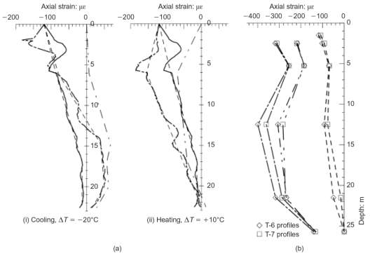
The in-situ tests produced some notable results, with the most important of these strain profiles shown in Figure 8. These profiles demonstrated that the pile strains were significantly affected by the temperature cycles and that tensile strains were generated in the cooling case.
The results produced from these in-situ tests were the basis for the framework described above. As can be seen from Figure 8 the in-situ testing approximately follows the expected profiles: Lambeth College and Figure 7a and Figure 7b; Lausanne and Figure 7c and Figure 7d. This assists somewhat to explain energy pile behaviour, however, is limited to the two sites where the investigations were performed.
Restraints surrounding in-situ testing of energy piles have led to the development of a number of numerical models, which aim to further the current understanding. Most methods utilise finite elements with two popular approaches applied:
The t-z load transfer curve has been successfully utilised by Ouyang, et al. (2011) and Knellwolf, et al. (2011), to back-analyse the Lambeth College and Lausanne field tests producing a good correlation between results. Similar simulations have been performed by Gawecka, et al. (2016) with comparable outcomes. Thus, previous numerical tests have demonstrated via back-analysis that they are a viable method to analyse the behaviour of energy piles. However, as this approach is still relatively new, literature has not advanced much past developing and validating these models.
Research has now provided a solid understanding of energy pile strain behaviour. However, tests regarding the mobilised bearing capacity and pile head displacements are currently limited, often produced alongside strain data for limited conditions without further exploration. Therefore, a gap in the knowledge remains surrounding the impact of temperature cycles on the mobilised bearing capacity and head displacements of energy piles for a variety of pile and soil properties.
This section outlines the finite element model, defining how it works and verifying it using a back-analysis against existing field data.
A finite element model developed in MATLAB is to be used to conduct a parametric study of an energy pile. This model adopts a t-z beam spring method where the pile is split into a number of equally sized, linear beam elements connected by nodes, as shown in Figure 9.
Each node has one degree of freedom, due to free vertical movements. The local beam element stiffness matrix, kEL, is based on standard finite element formulation, (Bathe, 2014):
kEL, pile=EALEL1-1-11
(5)
The soil is simplified as a series of nonlinear springs which connect to the beams simulating the pile-soil interaction. Each spring has one degree of freedom, due to free vertical movement, with the stiffness of the spring, kspring, based upon the load transfer (t-z) curve, shown in Figure 10.
kspring=tz
(6)
The t-z curve defines the shaft friction, t, and pile displacements, z, due to the pile-soil interaction. Maximum shaft friction can be calculated for drained and undrained conditions, (Craig & Knappett, 2012):
tm, undrained=αSuAs
(7)
tm, drained=K0σv’tanφ’As
(8)
Where the terms are defined; soil adhesion factor, α; undrained shear strength of soil, Su; area of pile in contact with soil, As; coefficient of earth pressure, K0; effective vertical soil stress,
σv’; soil friction angle, δ’.
The maximum stiffness for displacement, km, was defined by Randolph and Wroth (1978):
km=Grln2.5L(1-ν)γ
(9)
Where the terms are defined; soil shear modulus, G; pile radius, r; pile length, L; soil Poisson’s ratio, ν; soil unit weight, γ.
The shaft friction along the load transfer curve has subsequently been defined, (Pelecanos, et al., 2018):
t=kmz1+kmztmhdd
(10)
Where the terms are defined; hardening parameter, h; degradation parameter, d.
Substituting into Equation 6 allows the calculation of the local spring stiffness. The global stiffness matrices for the pile, kp, and the soil, ks, can then be formed by combining the local values for each element. Considering the equilibrium of the model an expression for pile displacements can be derived, (Bathe, 2014):
P=ku
(11)
Displacements, u, are calculated by multiplying the applied mechanical loads, P, against the inverse of the combined global stiffness matrix, k. Where
k=kp+ksthe equation can be stated:
P=kp+ksu
(12)
However, in the case of thermomechanical analysis temperature loading, specified by Equation 4, will also need to be included within the equilibrium equation:
P + αcEA∆T=kp+ksu
(13)
Thus, when the properties and loading are specified the finite element model is able to determine the unknown displacement values.
The finite element model will now be validated by performing a back-analysis of a known field study and comparing the test results to ensure that the model appropriately simulates energy pile behaviour.
Bourne-Webb, et al. (2009) conducted one of the first energy pile field tests at the Clapham Centre of Lambeth College, South London. The study was performed prior to construction of a five storey building supported on 143 bored pile foundations all of which were utilised as a GSHP system. The experiment aimed to determine the behaviour of a single test pile for cycles of heating and cooling under a sustained load (Bourne-Webb, et al., 2009).
The 23m test pile, shown in Figure 11, was designed based purely on the geotechnical requirements with a safety factor of 2.5. The pile diameter varied with depth, 0.610m for the first 5m and 0.550m for the subsequent 18m. U-shaped heat exchanger loops were attached to 32mm reinforcement which extended for the full length of the pile. Continuous strain and temperature measurements were supplied by 18 vibrating-wire strain gauges, 6 thermistors and optical fibre sensors (Bourne-Webb, et al., 2009).
Ground conditions are shown in Figure 11, showed 1.5m of made ground and 2.5m of terrace gravel overlying a layer of London clay. The groundwater table was found within the terrace gravel at depth 3m. Throughout testing a mechanical load of 1200kN was sustained through several cycles of heating and cooling. As seen from Figure 12, the temperature change under cooling ~∆T=-18℃ and ~∆T=+10℃ under heating (Bourne-Webb, et al., 2009).
Testing was conducted in over a three month period in 2007, with the series of tests specified below:
The study results, displayed in Figure 8a, significantly improved the understanding of energy pile behaviour. The Lambeth College study has subsequently been successfully used to by multiple studies validate numerical models (Ouyang, et al., 2011; Gawecka, et al., 2016; Knellwolf, et al., 2011). Therefore, a back-analysis of this field data will be performed using the finite element model.
Three tests were conducted and compared to Lambeth College data, with the parameters based upon data obtained from a previous back-analysis by Ouyang, et al., (2011). The applied loading and model parameters are displayed in the tables below.
Table 1: Verification Model Loading
| Test | Mechanical Load | Thermal Load |
| Mechanical | 1.2MN | ΔT = 0°C |
| Heating | 1.2MN | ΔT = +10°C |
| Cooling | 1.2MN | ΔT = -18°C |
Table 2: Verification Model Pile Properties
| Pile Properties | Mechanical Load |
| Length, L (m) | 23 |
| Diameter, d (m) | 0.610 for Depth 0-5m |
You Want The Best Grades and That’s What We Deliver
Our top essay writers are handpicked for their degree qualification, talent and freelance know-how. Each one brings deep expertise in their chosen subjects and a solid track record in academic writing.
We offer the lowest possible pricing for each research paper while still providing the best writers;no compromise on quality. Our costs are fair and reasonable to college students compared to other custom writing services.
You’ll never get a paper from us with plagiarism or that robotic AI feel. We carefully research, write, cite and check every final draft before sending it your way.